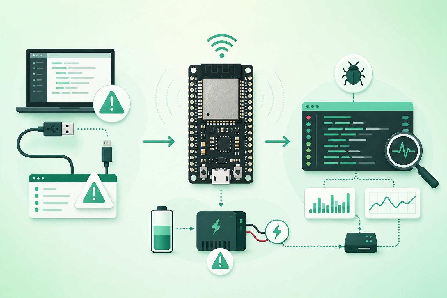
ESP32 boards are popular because a small development board can combine:
microcontroller
Wi-Fi
Bluetooth
GPIO
ADC
PWM
serial interfaces
low-power modes
That flexibility also creates many ways for a first project to fail.
A board that refuses to upload may have perfectly good firmware.
A program that crashes when Wi-Fi starts may actually have a weak power supply.
A sensor that behaves strangely may be attached to a GPIO with a special startup function.
The fastest debugging strategy is therefore not:
change code
change library
change pins
change board
change power supply
all at once
It is:
simplify
observe
change one variable
verify
then reconnect complexity
Remember that “ESP32” is a family
Pin behavior, native USB support, flash configuration, peripheral availability and boot requirements can differ between ESP32 variants and development boards. Always check the documentation and schematic for the exact board or module you are using rather than applying one random pinout to every ESP32.
1. Identify the exact ESP32 board first
Before debugging firmware, identify:
chip family
development board
module
flash configuration
USB interface
Examples of ESP32-family devices can differ substantially in peripheral layout and USB behavior.
Read the module marking
The metal-shielded module or board silkscreen often contains useful model information.
Find the board schematic
A schematic reveals:
- USB interface.
- Voltage regulator.
- BOOT wiring.
- EN/reset circuit.
- LED connections.
- Exposed GPIO.
Do not copy pin numbers blindly
A tutorial may say:
LED = GPIO 2while your board may use:
another GPIO

or

no onboard LED at all
2. Start with a minimal known-good setup
ESP32 setup and debugging flow (diagram)
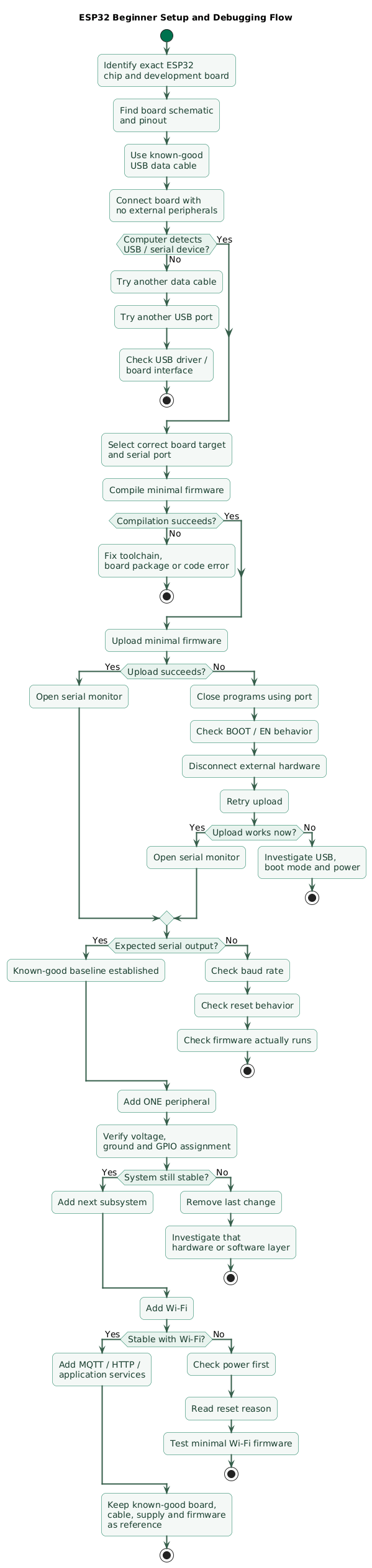
When debugging a new board, disconnect almost everything.
computer
   ↓
known-good USB data cable
   ↓
ESP32 development board
No relay.
No display.
No motor.
No sensor board.
Upload minimal firmware
Start with something that does almost nothing:
initialize serial

print:
"booted"

wait

repeat
If this fails, the sensor library is not the problem.
Establish a baseline
Confirm:
- The board powers on.
- The computer detects the expected port.
- Firmware uploads.
- The board resets normally.
- The serial monitor receives output.
Only then reconnect external components.
3. Diagnose upload and serial-port failures
Upload problems often happen before your application firmware even runs.
Check the USB cable
Some cables provide power but no usable data connection.
Symptoms:
board LED turns on

but

no new serial / USB device appears
Try a cable already proven to transfer data.
Check the selected port
Disconnect the board.
Observe the port list.
Reconnect it.
The new device is usually the best candidate.
Close programs using the port
Uploading may fail if another process already owns the serial interface.
Examples:
- Another IDE instance.
- Serial terminal.
- Background logging program.
Check the board target
Selecting an incompatible target can produce:
- Upload failures.
- Wrong flash configuration.
- Unexpected peripheral definitions.
- Boot loops.
Do not start by reinstalling everything
First isolate:
USB
port
board target
boot mode
power
before replacing libraries or rewriting application code.
4. Understand BOOT, EN, and download mode
ESP32 devices contain a ROM bootloader that can accept new firmware under the appropriate startup conditions.
Typical development-board controls
BOOT:
influences download-mode entry

EN / RESET:
resets the chip
Exact behavior depends on the development board.
Automatic reset usually handles this
Many development boards use USB-to-serial control signals to automatically manipulate reset and boot conditions during upload.
Manual boot sequence can help diagnose failures
On boards designed for this workflow, the general pattern is:
hold BOOT
      ↓
reset / begin upload
      ↓
release BOOT
after connection begins
Follow the specific board documentation if its behavior differs.
External circuitry can break boot
Some GPIO levels are sampled during reset to select startup behavior.
If an external circuit forces one of those signals:
HIGH
or
LOW
at the wrong moment, the device may enter an unexpected mode.
A classic clue is:
board boots normally
with sensor disconnected

board fails to boot
with sensor connected
5. Treat random resets as a possible power problem
ESP32 power and reset troubleshooting (diagram)
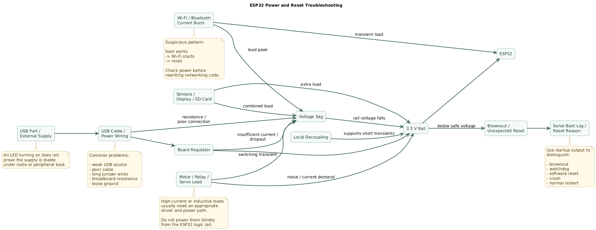
A common beginner assumption is:
LED is on
therefore power is fine
This is not sufficient.
The board may power an LED while the supply still collapses briefly during radio activity.
Power path matters
USB supply
  ↓
cable
  ↓
connector
  ↓
board regulator
  ↓
3.3 V rail
  ↓
ESP32 + peripherals
Resistance and current limitations can appear anywhere in this path.
Breadboards add resistance and uncertainty
Long jumper wires and poor contacts can create voltage drops that are invisible when measuring an unloaded supply.
Peripheral loads add up
A board may also power:
display
sensor
relay module
SD card
GPS module
LED strip
other radio
through a regulator never intended for the combined load.
Do not power motors directly from the ESP32 rail
Motors, servos, relays and other inductive or high-current loads generally need an appropriate power design.
Their switching noise and current demand can destabilize the microcontroller supply.
6. Debug brownouts and Wi-Fi-related resets
Radio activity can produce a much more demanding load than idle firmware.
This pattern is suspicious:
boot
serial prints normally
Wi-Fi starts
reset

boot
Wi-Fi starts
reset
Suspect the supply before rewriting networking code
Check:
- USB cable.
- USB port or adapter.
- External supply capability.
- Regulator rating.
- Ground connections.
- Wiring length.
- Local decoupling.
Measure the rail during the failure
A multimeter can show average voltage.
Fast voltage drops are easier to investigate with an oscilloscope.
Do not “fix” brownouts by hiding the warning
Disabling protection or ignoring reset messages does not improve an inadequate supply.
Fix the electrical cause.
Separate ESP32 power from noisy loads
Where the circuit requires it:
main supply
   ├── regulated clean rail → ESP32
   │
   └── appropriate driver / supply → load
with proper grounding, protection and decoupling.
7. Choose GPIO pins carefully
ESP32 GPIO and boot-pin debugging guide (diagram)
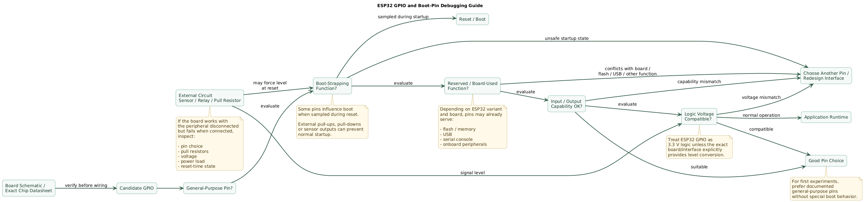
Not every exposed pin is equally convenient.
Depending on the exact ESP32 variant and module, some signals can be tied to:
- Boot configuration.
- Flash or external memory.
- USB.
- Serial debugging.
- Input-only behavior.
- Other special peripheral functions.
Check three things before selecting a GPIO
1. Is it exposed by this board?

2. Does it have a boot or internal function?

3. Can the peripheral force it during reset?
Boot-strapping pins deserve special attention
These pins can be sampled during startup.
External:
pull-up
pull-down
sensor output
relay input circuit
can therefore influence boot behavior.
Board labels and GPIO numbers may differ
Always distinguish:
physical header position

from

GPIO number
Use simple pins first
For a first LED, button or sensor experiment, choose a documented general purpose pin without special startup requirements.
8. Respect 3.3-volt logic and peripheral power
ESP32 GPIO should generally be treated as:
3.3 V logicunless the exact interface and board documentation explicitly provides level conversion.
Do not connect arbitrary 5 V outputs directly
A sensor module may be powered from 5 V while also producing a 5 V logic output.
That can require:
level shifter
or
resistor divider
or
3.3 V-compatible sensor mode
depending on the signal.
Check breakout boards, not just sensor chips
A breakout may contain:
- Regulator.
- Pull-up resistors.
- Level shifting.
- LEDs.
The raw sensor datasheet does not necessarily describe the finished breakout board.
I2C pull-ups matter
Several I2C modules may each contain pull-up resistors.
Multiple parallel pull-ups can produce a stronger effective pull-up than expected.
Share ground when signals are shared
Two separately powered circuits normally need an appropriate common signal reference when directly exchanging non-isolated digital signals.
9. Fix floating inputs and unreliable sensors
An unconnected digital input does not automatically read:
0It can float between states.
Typical symptom
button not pressed

but firmware randomly reports:

pressed
not pressed
pressed
Use defined logic levels
Depending on the circuit:
pull-up
or
pull-down
ensures the input has a known state when the switch or sensor is inactive.
Internal pulls can help
Many GPIO configurations support internal pull resistors, but their availability and exact behavior should be verified for the selected pin and ESP32 variant.
Mechanical switches bounce
A button transition may physically produce:
0
1
0
1
1
over a short interval.
Use:
software debounce

or

hardware debounce
where appropriate.
Analog readings need realistic expectations
ADC behavior can depend on:
- Chip variant.
- Input range.
- Attenuation or configuration.
- Noise.
- Calibration.
- Other active peripherals.
Do not assume an ADC reading is a laboratory-grade voltage measurement without calibration and validation.
10. Separate Wi-Fi problems from firmware problems
Start with clear connection logs
boot
Wi-Fi start
connecting...
connected
IP acquired
is much easier to diagnose than:
nothing happensCheck credentials carefully
Common problems include:
- Wrong network name.
- Wrong password.
- Unexpected spaces.
- Configuration copied from another environment.
Check network compatibility
Confirm that the selected ESP32 device and firmware configuration support the wireless network mode you are trying to use.
Do not loop forever without visibility
Bad debugging pattern:
while not connected:
    wait forever
Better:
attempt connection
    ↓
log state
    ↓
timeout
    ↓
retry with delay
or
continue in offline mode
Wi-Fi can expose power problems
If enabling Wi-Fi causes:
reset
freeze
brownout
test the power system before assuming the network library is broken.
11. Debug deep sleep and wake-up behavior
Deep sleep can make a perfectly healthy ESP32 appear dead.
Typical beginner sequence
boot
print message
enter deep sleep

serial monitor opened later

result:
apparently nothing happens
The device may already be asleep.
Add startup evidence
BOOT
reset reason
wake reason
counter
can make behavior much clearer.
Remember that deep sleep resembles a reboot
After wake-up, normal application state in RAM may not survive unless it is deliberately stored in a retention mechanism appropriate for the selected chip.
Verify wake source configuration
Depending on the ESP32 variant, wake sources can include combinations of:
- Timer.
- GPIO-related wake mechanisms.
- Touch or other supported peripherals.
Exact capabilities vary by chip.
Test sleep without external circuitry first
External pull resistors, sensors and level shifters can:
- Prevent expected wake behavior.
- Increase sleep current.
- Back-power the board.
12. Use serial logs, reset reasons, and minimal tests
Logging should answer:
How far did execution get?Add milestone logs
[BOOT] started
[INIT] sensor
[INIT] Wi-Fi
[WIFI] connected
[MQTT] connecting
[MQTT] connected
If the final line is:
[INIT] Wi-Fithe search area becomes much smaller.
Print important configuration
Useful non-sensitive values include:
firmware version
board mode
GPIO assignments
sensor address
network state
Do not print:
passwords
private keys
access tokens
Read reset information
Reset information can help distinguish:
- Normal reset.
- Watchdog reset.
- Brownout-related reset.
- Software-triggered restart.
- Sleep wake-up.
Watchdog resets are symptoms
A watchdog may indicate:
code blocked too long
deadlock
interrupt problem
task starvation
rather than a defective watchdog.
Build minimal reproductions
If a large project crashes:
copy only failing sensor code
into tiny project

test

then add Wi-Fi

test

then add MQTT
This exposes interactions much faster than debugging everything simultaneously.
13. Use a systematic debugging workflow
Step 1: remove external hardware
ESP32
+
USB only
Step 2: verify power
Confirm:
- Board powers consistently.
- No reset loop.
- Supply remains stable.
Step 3: verify upload
Use a known minimal program.
Step 4: verify serial output
Confirm:
correct port
correct baud rate
visible startup messages
Step 5: add one peripheral
ESP32
+
one sensor
Verify:
- Voltage.
- Ground.
- GPIO assignment.
- Bus address where relevant.
Step 6: add networking
Check whether adding Wi-Fi changes stability.
Step 7: add application services
MQTT
HTTP
TLS
cloud API
one layer at a time.
Step 8: reproduce the fault deliberately
A fault that occurs:
1 time in 100is much harder to diagnose than one you can trigger reliably.
Step 9: change one variable
Bad:
new cable
new code
new sensor
new pins
new supply
at the same time.
Better:
change cable

test

change supply

test

change pin

test
Step 10: keep a known-good baseline
Save:
known-good firmware
known-good board settings
known-good wiring
known-good power supply
so you can always return to a stable reference.
14. Copy/paste ESP32 troubleshooting checklist
ESP32 beginner troubleshooting checklist

Board identification
- Identify exact ESP32 variant.
- Identify exact development board.
- Read module marking.
- Find board schematic.
- Find official pinout.
- Confirm flash configuration.
- Confirm USB interface type.
- Do not assume all ESP32 boards are identical.

Development environment
- Install correct ESP32 support.
- Select correct target.
- Select correct board profile.
- Check flash settings.
- Check partition settings where relevant.
- Compile minimal program first.
- Avoid adding many libraries before baseline works.

USB cable
- Use known-good data cable.
- Avoid charge-only cables.
- Test another cable.
- Test another computer USB port.
- Avoid unreliable hubs during debugging.
- Inspect connector damage.

Serial port
- Disconnect board.
- Observe available ports.
- Reconnect board.
- Select newly appearing port.
- Close other serial programs.
- Reopen IDE if port state is stale.
- Verify OS recognizes USB device.

Upload
- Compile minimal sketch.
- Verify correct board.
- Verify correct port.
- Disconnect external hardware.
- Retry upload.
- Use manual BOOT sequence where appropriate.
- Inspect upload log.
- Do not change application code before solving connection problem.

BOOT
- Understand board BOOT button.
- Understand EN/reset button.
- Check automatic reset circuit.
- Check external circuits on boot-related pins.
- Disconnect peripherals if boot fails.
- Avoid forcing boot pins during reset.
- Follow exact board documentation.

EN / reset
- Verify EN is not being pulled low.
- Check external reset circuit.
- Check button operation.
- Check noise on reset line where relevant.
- Verify stable supply during reset.

Minimal baseline
- Board only.
- USB only.
- Minimal firmware.
- Serial output.
- No sensors.
- No display.
- No relay.
- No motor.
- No SD card.
- No external radio.

Serial logging
- Initialize serial early.
- Use known baud rate.
- Print BOOT message.
- Print firmware version.
- Print initialization stages.
- Print network stages.
- Print error reason.
- Avoid logging passwords.
- Avoid logging private keys.
- Avoid logging tokens.

Power supply
- Check USB source.
- Check cable quality.
- Check regulator.
- Check voltage at ESP32.
- Check voltage during radio activity.
- Check ground.
- Check breadboard contacts.
- Check jumper length.
- Check peripheral current.

Brownout
- Look for brownout-related reset messages.
- Test without peripherals.
- Test without Wi-Fi.
- Use stronger known-good supply.
- Shorten power wiring.
- Improve local decoupling where design requires it.
- Measure rail during failure.
- Do not hide brownout protection instead of fixing supply.

Wi-Fi reset
- Reproduce with minimal Wi-Fi sketch.
- Remove other peripherals.
- Check supply.
- Check regulator heating.
- Check USB cable.
- Check serial reset reason.
- Test near access point.
- Separate RF problem from power problem.

Decoupling
- Follow module and board design recommendations.
- Place local capacitors appropriately in custom hardware.
- Avoid long high-impedance power paths.
- Consider peripheral transients.
- Check capacitor orientation where polarized.
- Check capacitor ESR where relevant.

Motors
- Do not drive motor directly from GPIO.
- Use appropriate driver.
- Use appropriate power supply.
- Handle inductive transients.
- Keep noisy current away from logic rail where practical.
- Verify common ground when required.
- Test motor startup current.

Relays
- Use proper relay driver.
- Check coil voltage.
- Check module input logic.
- Check optocoupler wiring where present.
- Handle inductive energy.
- Avoid powering large relay loads from weak board regulator.
- Test relay switching for resets.

Servos
- Use adequate external power.
- Do not assume USB regulator can supply servo peaks.
- Share signal reference appropriately.
- Test stall current.
- Watch supply sag.
- Add protection appropriate to design.

GPIO
- Check exact chip pin documentation.
- Check board schematic.
- Check boot-strapping role.
- Check internal flash connections.
- Check native USB pins where relevant.
- Check input-only limitations where relevant.
- Check whether board already uses pin.
- Prefer simple GPIO for first experiments.

Boot-strapping pins
- Identify them for exact chip.
- Check external pull-ups.
- Check external pull-downs.
- Check sensor outputs at reset.
- Check relay module inputs.
- Disconnect suspect peripheral.
- Verify normal boot.

Logic voltage
- Treat ESP32 GPIO as 3.3 V logic.
- Do not directly apply arbitrary 5 V logic.
- Check sensor output voltage.
- Use level shifting where required.
- Check breakout-board circuit.
- Do not assume 5 V supply means 3.3 V logic.

Ground
- Establish correct common reference where required.
- Check loose ground wire.
- Check breadboard ground rails.
- Remember some breadboards split rails.
- Measure continuity.
- Avoid ground loops in more complex systems.

Buttons
- Use pull-up or pull-down.
- Avoid floating input.
- Debounce mechanical switch.
- Verify active-high or active-low logic.
- Test button with simple sketch.

Floating inputs
- Never assume disconnected input is LOW.
- Configure pull resistor.
- Check long wires for noise.
- Avoid high-impedance unshielded runs where inappropriate.
- Confirm stable idle state.

I2C
- Verify SDA.
- Verify SCL.
- Verify device address.
- Verify supply voltage.
- Verify shared ground.
- Check pull-ups.
- Scan bus.
- Reduce bus speed if debugging signal-integrity problems.
- Check multiple breakout-board pull-ups.

SPI
- Verify clock.
- Verify MOSI.
- Verify MISO.
- Verify chip select.
- Check voltage.
- Check shared ground.
- Confirm peripheral mode.
- Check chip-select conflicts.
- Test one peripheral at a time.

UART
- Cross TX to RX where required.
- Connect ground.
- Match voltage levels.
- Match baud rate.
- Check whether selected pins conflict with console.
- Test with simple echo where useful.

ADC
- Check exact ADC-capable pins.
- Check allowed input range.
- Do not exceed GPIO voltage limits.
- Expect noise.
- Average where appropriate.
- Calibrate where accuracy matters.
- Check variant-specific peripheral limitations.
- Compare against known voltage.

PWM
- Verify target GPIO supports intended use.
- Verify frequency.
- Verify duty cycle.
- Check peripheral library configuration.
- Test LED before motor or power load.
- Use proper driver for high-current loads.

Sensors
- Read sensor datasheet.
- Read breakout-board documentation.
- Check supply voltage.
- Check logic voltage.
- Check required pull-ups.
- Check address.
- Check startup time.
- Test sensor alone.
- Verify raw data before adding cloud code.

Displays
- Test display alone.
- Verify voltage.
- Verify interface.
- Verify address.
- Verify reset pin.
- Verify required memory.
- Watch power consumption.
- Check library matches controller.

SD cards
- Use appropriate voltage and interface.
- Check peak current.
- Use short wiring.
- Check filesystem.
- Test card separately.
- Watch for power-related resets.
- Avoid assuming every breakout has proper level shifting.

Libraries
- Use library compatible with selected ESP32 environment.
- Check examples for same framework.
- Read compiler warnings.
- Avoid mixing incompatible APIs.
- Reduce project to smallest failing example.
- Upgrade libraries deliberately, not randomly.

Wi-Fi
- Verify SSID.
- Verify password.
- Check network mode compatibility.
- Log connection state.
- Add timeout.
- Add controlled retry.
- Avoid infinite silent connection loop.
- Test near access point.
- Check signal strength.
- Check power stability.

MQTT
- First prove Wi-Fi works.
- Verify broker hostname.
- Verify port.
- Verify TLS settings.
- Verify credentials.
- Log connection errors.
- Add reconnect backoff.
- Avoid tight reconnect loops.
- Test simple publish before complex subscriptions.

HTTP
- First prove Wi-Fi.
- Verify DNS.
- Verify endpoint.
- Verify TLS.
- Add timeout.
- Log status code.
- Limit retries.
- Close resources appropriately.

TLS
- Validate certificates.
- Keep device time considerations in mind.
- Check trust anchors.
- Do not disable certificate validation as a permanent fix.
- Watch RAM usage on constrained builds.
- Separate TLS errors from Wi-Fi errors.

Deep sleep
- Print message before sleep.
- Print wake reason after boot.
- Verify timer configuration.
- Verify wake-capable pins for exact chip.
- Check external pull resistors.
- Check retained state assumptions.
- Measure real sleep current.
- Test without peripherals.

Sleep current
- Development boards may consume more than bare modules.
- USB bridge can consume power.
- Regulator quiescent current matters.
- Power LED can consume power.
- Sensors may remain active.
- Pull-ups consume current.
- Measure complete board.
- Do not compare dev-board sleep directly with bare-chip headline numbers.

Watchdog
- Read reset message.
- Look for blocking loops.
- Look for deadlocks.
- Avoid long unyielding work.
- Check task behavior.
- Check interrupt behavior.
- Do not disable watchdog merely to hide firmware problems.

Crashes
- Capture serial output.
- Save backtrace where available.
- Record firmware version.
- Reproduce with minimal code.
- Remove peripherals.
- Check power.
- Check memory usage.
- Check stack usage.
- Check invalid pointers and buffer bounds.

Memory
- Watch large global buffers.
- Watch dynamic allocation.
- Watch large JSON documents.
- Watch image buffers.
- Watch TLS memory.
- Avoid accidental memory leaks.
- Monitor free heap where useful.

Reset loops
- Capture first boot messages.
- Identify reset reason.
- Test minimal firmware.
- Disconnect peripherals.
- Verify power.
- Verify flash configuration.
- Verify firmware target.
- Check watchdog.
- Check boot pins.

Breadboard
- Check rails are connected.
- Some rails are split.
- Check loose jumper wires.
- Avoid extremely long wires.
- Verify pin placement.
- Check power polarity.
- Test continuity.
- Replace suspect breadboard.

Multimeter
- Measure supply voltage.
- Measure continuity.
- Check ground.
- Check sensor supply.
- Check divider outputs.
- Remember a multimeter may miss short voltage dips.

Oscilloscope
- Inspect 3.3 V rail.
- Inspect reset line.
- Inspect digital buses.
- Inspect radio-related power dips.
- Inspect switching noise.
- Use proper probing techniques.

Logic analyzer
- Inspect I2C.
- Inspect SPI.
- Inspect UART.
- Confirm timing.
- Confirm addresses.
- Confirm messages.
- Useful when software says communication failed but wiring appears correct.

Debug sequence
- Remove everything.
- Verify board identity.
- Verify USB data cable.
- Verify serial port.
- Verify board target.
- Upload minimal firmware.
- Verify serial logs.
- Verify stable power.
- Add one peripheral.
- Test.
- Add Wi-Fi.
- Test.
- Add cloud service.
- Test.

One variable at a time
- Change one wire.
- Test.
- Change one GPIO.
- Test.
- Change one library version.
- Test.
- Change one power source.
- Test.
- Record result.

Known-good references
- Keep known-good USB cable.
- Keep known-good board.
- Keep known-good supply.
- Keep minimal firmware.
- Keep verified pinout.
- Keep working sensor example.
- Compare failing system against baseline.

Documentation
- Record exact board model.
- Record chip variant.
- Record framework version.
- Record library versions.
- Record GPIO mapping.
- Record supply voltage.
- Record wiring.
- Record reset reason.
- Record failure conditions.

Final review
- Do I know the exact ESP32 board?
- Is the USB cable data-capable?
- Is the correct port selected?
- Is the correct board target selected?
- Can minimal firmware upload?
- Can I see serial logs?
- Does the board run with no peripherals?
- Is the supply stable?
- Does Wi-Fi trigger a reset?
- Are GPIO levels limited appropriately?
- Am I using a boot-related pin?
- Is an external circuit forcing a pin during reset?
- Are inputs floating?
- Do all peripherals share the correct reference?
- Is the sensor powered at the correct voltage?
- Are pull-ups correct?
- Is a motor or relay disturbing the supply?
- Do I know the reset reason?
- Can I reproduce the problem with minimal code?
- Have I changed only one variable at a time?
15. FAQ
Why will my ESP32 not upload?
Start with the USB cable, serial port and target-board selection. Confirm that the cable supports data, no other application is holding the serial interface, and the board can enter its download mode. Disconnect external hardware that might interfere with boot-related GPIO.
Why does my ESP32 keep resetting?
Read the startup log and reset reason. Common areas to investigate include unstable power, brownout, watchdog timeouts, firmware crashes, incorrect flash configuration and external circuitry affecting reset or boot pins.
Why does the ESP32 reset when Wi-Fi connects?
Radio activity increases the instantaneous load on the power path. A weak USB source, poor cable, inadequate regulator, long breadboard wiring or insufficient decoupling can therefore become visible only when Wi-Fi starts transmitting.
Can I connect a 5 V sensor to an ESP32?
The sensor's power supply voltage and its digital logic voltage are separate questions. ESP32 GPIO should generally be treated as 3.3 V logic, so verify the sensor output levels and use appropriate level conversion when needed.
Why does my ESP32 stop booting after I connect a sensor?
The sensor may be connected incorrectly, drawing down the supply, forcing a boot-strapping GPIO, using an inappropriate voltage or conflicting with a board-specific pin function. Disconnect it and verify each connection independently.
Why does my input randomly change between HIGH and LOW?
The input may be floating. Configure an appropriate pull-up or pull-down resistor and check the wiring. Mechanical switches may additionally need debounce handling.
What is the fastest way to debug a complicated ESP32 project?
Reduce it to the smallest known-good configuration, prove power, upload and serial operation, then add one subsystem at a time. A reproducible minimal failure is usually much easier to diagnose than a complete application containing Wi-Fi, sensors, displays, MQTT and other peripherals at once.
Key terms (quick glossary)
- ESP32
- A family of microcontrollers and system-on-chip devices commonly used in connected embedded and IoT projects.
- Development board
- A PCB containing an ESP32 module or chip plus supporting components such as regulators, USB interfaces, buttons, headers and status LEDs.
- BOOT
- A label commonly used on development boards for a control involved in selecting or assisting entry into the firmware-download boot mode.
- EN
- Enable or reset-related signal commonly used to restart the ESP32.
- Bootloader
- Firmware or ROM code responsible for early startup and loading the application or entering a programming mode.
- Strapping pin
- A pin whose logic level is sampled during reset to influence boot or chip configuration.
- Brownout
- A condition where supply voltage falls below the level required for reliable operation, potentially triggering a protective reset.
- Decoupling capacitor
- A capacitor positioned to reduce local supply noise and provide charge during short load transients.
- GPIO
- General-purpose input/output pin used for digital input, digital output or selected peripheral functions.
- Pull-up
- A resistor or internal circuit that biases a signal toward a defined logic-high level when nothing else actively drives it.
- Pull-down
- A resistor or internal circuit that biases a signal toward a defined logic-low level when nothing else actively drives it.
- Floating input
- A high-impedance input without a defined electrical level, allowing noise to produce unpredictable readings.
- Serial monitor
- A terminal used to view diagnostic text sent by firmware over a serial or USB communication interface.
- Watchdog
- A hardware or software mechanism that detects code which stops making expected progress and may reset the system.
- Deep sleep
- A low-power mode that shuts down substantial parts of the chip while retaining only the resources required for the selected wake mechanism.
- ADC
- Analog-to-digital converter used to measure an analog voltage and represent it digitally.
- Level shifter
- A circuit that converts digital signaling between different voltage domains, such as 5 V and 3.3 V logic.
Worth reading
Recommended guides from the category.