The simplest battery-life equation looks almost too easy:
Battery life [hours]
=
Battery capacity [mAh]
/
Average current [mA]
The equation is useful.
The difficult part is obtaining an average current and usable battery capacity that represent the real product.
An IoT sensor does not normally consume one constant current. It moves through states:
deep sleep
    ↓
wake MCU
    ↓
power sensor
    ↓
measure
    ↓
process
    ↓
start radio
    ↓
connect / transmit
    ↓
receive acknowledgement
    ↓
store state
    ↓
sleep
A few milliseconds at tens of milliamps may coexist with minutes or hours at only a few microamps.
Good estimation turns this current waveform into charge consumption, averages it over time, then adjusts the theoretical result for the battery and environment.
Model charge, not just peak current
A 30 mA radio event is not necessarily expensive if it lasts only a few milliseconds. A 20 µA leakage path can be extremely expensive if it remains active every second for several years. Current and duration must always be considered together.
1. Model the device as a sequence of power states
IoT sensor duty-cycle current model (diagram)
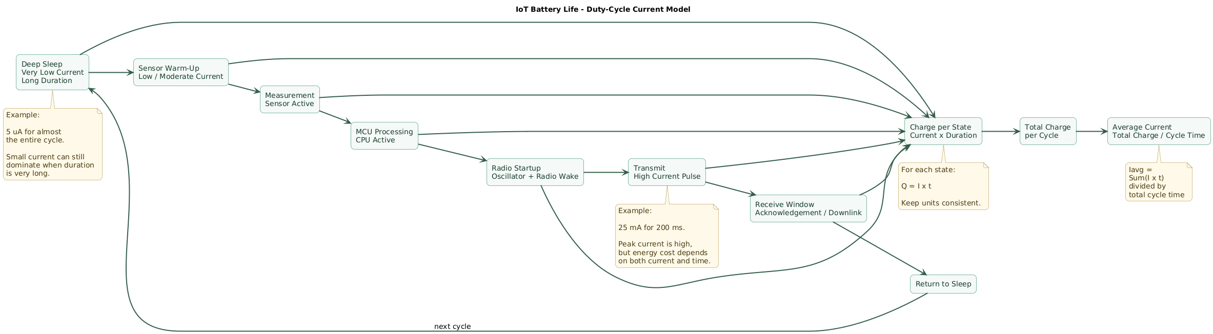
Start with one representative operating cycle.
For a sensor reporting every ten minutes, the cycle is:
600 secondsBreak that interval into states.
| State | Example current | Example duration |
|---|---|---|
| Sleep | 5 µA | 599.7 s |
| Sensor measurement | 2 mA | 50 ms |
| MCU processing | 5 mA | 50 ms |
| Radio TX/RX event | 25 mA | 200 ms |
The numbers above are illustrative. Replace every value with measurements or appropriate datasheet values from your actual hardware.
Represent every meaningful state
A realistic device may need more states:
deep sleep
RTC wake
sensor warm-up
ADC measurement
flash write
cryptographic operation
radio scan
network association
DNS
TLS handshake
transmission
receive window
firmware update
Not every state happens every cycle
Some operations happen:
every 5 minutes:
measurement

every hour:
cloud upload

every day:
clock synchronization

every month:
certificate check

occasionally:
firmware update
Convert these events into an average contribution over a common time period.
2. Calculate average current from current and time
For each state:
charge contribution
=
current × duration
Then sum the contributions and divide by total cycle time:
Iavg
=
(I1 × t1 + I2 × t2 + ... + In × tn)
/
Tcycle
Keep units consistent.
Using milliamps and seconds
For the example:
Sleep:
0.005 mA × 599.7 s
= 2.9985 mA·s

Sensor:
2 mA × 0.05 s
= 0.1 mA·s

MCU:
5 mA × 0.05 s
= 0.25 mA·s

Radio:
25 mA × 0.2 s
= 5 mA·s
Total:
2.9985
+ 0.1
+ 0.25
+ 5
=
8.3485 mA·s
Average current:
8.3485 mA·s
/
600 s
=
0.01391 mA

≈ 13.9 µA
This is the first important result.
Why the peak alone is misleading
The radio consumes:
25 mAbut only for:
0.2 seconds
out of 600 seconds
Its contribution is significant, but the device does not consume 25 mA continuously.
Why the sleep current still matters
The sleep current is only:
5 µAbut it persists for almost the entire cycle.
In this example:
sleep charge:
2.9985 mA·s

radio charge:
5 mA·s
Sleep therefore consumes a surprisingly large fraction of the cycle budget.
3. Convert average current into ideal battery life
Once average current is known:
Lifetime [hours]
=
Capacity [mAh]
/
Average current [mA]
Example with 235 mAh
Suppose the battery has a nominal capacity of:
235 mAhand the modeled average current is:
0.01391 mAThe ideal calculation is:
235
/
0.01391
≈
16,895 hours
Convert to days:
16,895 / 24
≈ 704 days
Convert to years:
704 / 365
≈ 1.93 years
1.93 years is not yet a product claim
This result assumes that every nominal milliamp-hour can be used under the device's load and environment. Real designs must account for cutoff voltage, discharge rate, pulse current, temperature, self-discharge, aging, regulator losses, retries, component tolerances, battery variation, and unexpected device activity.
Apply a first usable-capacity margin
If an engineering model initially assumes only 80% of nominal capacity is reliably usable:
235 mAh × 0.80
=
188 mAh
then:
188
/
0.01391
≈
13,515 hours

≈ 563 days

≈ 1.54 years
The 80% factor is an illustrative engineering margin, not a universal battery property. Derating should come from the selected cell's datasheet, measured load profile, temperature range, cutoff voltage, aging requirement, and desired confidence level.
4. Work through a practical sensor example
Consider a BLE environmental sensor that wakes every five minutes.
Cycle
Tcycle = 300 secondsMeasured states
| Operation | Current | Duration per cycle |
|---|---|---|
| Deep sleep | 3 µA | 299.82 s |
| Sensor warm-up | 1.5 mA | 80 ms |
| Measurement + MCU | 4 mA | 40 ms |
| BLE advertising burst | 8 mA | 60 ms |
Convert sleep current
3 µA
=
0.003 mA
Calculate charge contribution
Sleep:
0.003 × 299.82
=
0.89946 mA·s

Sensor:
1.5 × 0.08
=
0.12 mA·s

MCU:
4 × 0.04
=
0.16 mA·s

BLE:
8 × 0.06
=
0.48 mA·s
Total:
1.65946 mA·sAverage:
1.65946 / 300
=
0.00553 mA

=
5.53 µA
Ideal runtime with a 235 mAh cell
235 / 0.00553
≈
42,495 hours

≈
4.85 years
This is where many spreadsheet estimates stop.
A production estimate should continue.
Add background electronics
Suppose the board also contains:
regulator quiescent:
1.5 µA

voltage divider leakage:
2 µA

sensor standby:
0.7 µA
Total additional continuous load:
4.2 µANew average:
5.53 + 4.2
=
9.73 µA
Ideal runtime now becomes:
235 mAh / 0.00973 mA
≈
24,152 hours

≈
2.76 years
Several tiny leakage paths almost halved the theoretical result.
5. Use usable capacity, not just the number on the battery
Battery-life estimation workflow (diagram)
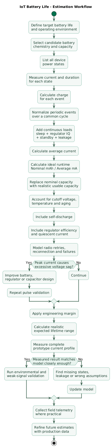
A battery's printed capacity is measured under specific test conditions.
For example, one commonly used CR2032 datasheet lists a typical capacity around 235 mAh under a relatively light continuous load at room temperature and to a specified cutoff voltage.
Your IoT device may operate under very different conditions.
Capacity depends on discharge conditions
Relevant variables include:
- Load current.
- Pulse current.
- Temperature.
- Cutoff voltage.
- Storage time.
- Cell chemistry.
- Manufacturing variation.
Your circuit has a minimum operating voltage
Suppose a battery still contains charge but its loaded voltage has fallen below:
MCU minimum voltage

or

radio minimum voltage

or

regulator dropout boundary
that remaining charge may not be usable by the product.
Model usable capacity explicitly
Usable capacity
=
Nominal capacity
× capacity factor
For example:
235 mAh
× 0.80
=
188 mAh
Again, the factor must be justified for the specific product rather than copied blindly.
Use datasheet discharge curves
Look for graphs showing:
- Voltage versus discharge time.
- Capacity versus load.
- Temperature behavior.
- Pulse response.
- Internal-resistance growth.
These often reveal limitations that the nominal mAh number hides.
6. Check pulse current and voltage sag
Average current can predict energy consumption while still missing a critical failure mode.
Radio transmitters often demand short high-current pulses.
average current:
15 µA

radio pulse:
40 mA
A small battery may contain plenty of remaining charge but struggle to provide the instantaneous current without excessive voltage drop.
Simple internal-resistance model
Voltage drop
≈
Current pulse × internal resistance
For example:
pulse current:
30 mA

effective internal resistance:
20 ohms

drop:
0.03 A × 20 ohms
=
0.6 V
A nominal 3 V cell could temporarily appear near:
2.4 Vbefore considering other dynamic effects.
If the device requires more than that voltage, it may reset.
Internal resistance changes over life
Cells do not maintain identical pulse capability from new to nearly depleted.
Aging, state of charge and temperature can increase the effective source resistance.
Test cold conditions
Low temperature can reduce battery voltage and available performance.
A device that works at:
21°Cmay fail during radio transmission at:
0°C
or
-10°C
even though a room-temperature capacity calculation predicts months of remaining runtime.
Capacitors can help with transients
A correctly selected low-ESR capacitor near the radio can supply part of a short pulse:
battery
   ↓
capacitor
   ↓
radio pulse
But capacitor sizing must account for:
- Pulse duration.
- Allowed voltage droop.
- ESR.
- Leakage current.
- Temperature.
- Recharge time.
7. Do not underestimate sleep current
Battery IoT products often spend more than 99% of their time asleep.
Every always-on microamp therefore matters.
One microamp per year
Continuous 1 µA consumption uses approximately:
0.001 mA × 8760 hours
=
8.76 mAh per year
Five unnecessary microamps consume:
43.8 mAh per yearOn a small coin cell, that can be a substantial part of the total energy budget.
Common hidden sleep loads
- Regulator quiescent current.
- Sensor standby modes.
- Voltage dividers.
- Pull-up resistors.
- LED indicators.
- USB interface chips.
- External flash.
- Secure elements.
- Debug circuitry.
Voltage divider example
A permanent divider:
3 V
across
100 kOhm total resistance
draws approximately:
I = V / R

3 / 100,000
=
30 µA
That one divider could consume more than an aggressively optimized MCU in deep sleep.
Switch measurement circuits where appropriate
Instead of continuously powering a divider or sensor:
GPIO / load switch ON
      ↓
measure
      ↓
GPIO / load switch OFF
can reduce continuous leakage, provided the electrical design remains safe and measurements remain accurate.
8. Model radio retries and reconnection
The optimistic radio model is:
wake
transmit once
success
sleep
Production looks more like:
wake
scan
connect
transmit
timeout
retry
receive
disconnect
sleep
Model success and failure separately
Suppose:
successful upload:
5 mA·s

failed attempt:
7 mA·s

90% succeed first try
10% need one retry
Expected radio charge becomes:
5
+
(0.10 × 7)
=
5.7 mA·s per reporting event
The average model should include this expected retry cost.
Weak signal can dominate power use
Poor connectivity may cause:
- Longer scans.
- Higher transmit power.
- Packet retransmission.
- Repeated association attempts.
- Longer receive windows.
Wi-Fi connection setup matters
A deeply sleeping Wi-Fi sensor may perform:
radio startup
    ↓
scan
    ↓
association
    ↓
DHCP or network restoration
    ↓
DNS
    ↓
TLS
    ↓
application request
Connection overhead can exceed the energy needed to transmit the actual sensor payload.
BLE interval choices matter
Battery consumption can change with:
- Advertising interval.
- Connection interval.
- PHY.
- Transmit power.
- Number of packets.
- Scanning behavior.
LoRaWAN airtime matters
Lower data-rate configurations can increase time on air.
A battery model should therefore use:
actual expected data rate
+
actual payload
+
expected retries
+
receive windows
rather than one generic “LoRa transmission” value.
9. Include regulators and supporting electronics
Measuring only the microcontroller current misses the product.
Regulator quiescent current
A regulator can consume current even when the application load is asleep.
MCU sleep:
2 µA

regulator IQ:
8 µA

real baseline already:
10 µA
Choosing a low-quiescent-current regulator can therefore be important.
Efficiency varies with load
A switching regulator advertised as:
95% efficientmay achieve that only within specific voltage and load regions.
IoT products move between:
microamp sleep
and
tens-of-milliamps radio bursts
so inspect efficiency curves across the actual range.
Linear regulator relationship
For a simple linear regulator, output current is approximately drawn from the input plus regulator overhead.
Energy efficiency also depends strongly on:
Vout / Vinbecause excess voltage is dissipated as heat.
Buck and boost converters
For switching converters, think in power:
Pin
≈
Pout / efficiency
and:
Pin = Vin × Iin

Pout = Vout × Iout
Do not assume battery current equals load current when voltages differ.
Include everything connected to the battery
MCU
radio
sensor
flash
secure element
regulator
LED
divider
pull-ups
charger
battery monitor
level shifter
debug interface
10. Account for temperature, aging, and self-discharge
Battery-life pitfalls and margin stack (diagram)
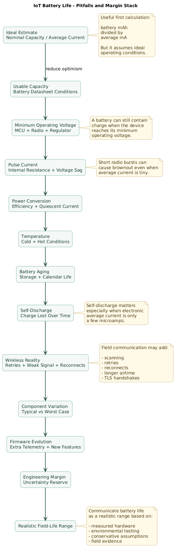
Self-discharge
Batteries lose charge even when the product consumes nothing.
For long-life designs, self-discharge becomes comparable to the electronic load.
As one concrete example, a CR2032 datasheet can specify self-discharge on the order of about 1% per year under its stated conditions.
Use the datasheet for the exact cell you intend to ship.
Temperature
Cold conditions can reduce available voltage and load capability.
High temperature can accelerate aging and self-discharge.
Test the full specified operating environment rather than only a laboratory bench at room temperature.
Battery aging
A battery can spend months in:
manufacturing
warehouse
distribution
retail inventory
before the customer activates the device.
Product lifetime should consider:
manufacture date
to
end of useful service
not only:
first customer boot
to
battery empty
Component tolerances
Sleep current in a datasheet may have:
typical value
and
maximum value
Production estimates should consider realistic worst-case parts, temperature and manufacturing variation.
Firmware evolves
Version 1 may report:
once every 30 minuteswhile version 2 adds:
more telemetry
extra retries
more frequent health checks
additional encryption
new diagnostics
Battery-life regression testing should therefore be part of firmware release testing.
11. Measure the real current profile
Datasheets are useful during architecture design.
Production predictions should eventually use the real board.
A normal multimeter may not be enough
An IoT waveform can range from:
2 µA sleep

to

40 mA radio pulse
across milliseconds.
A basic current meter may average away important transitions or introduce enough burden voltage to alter device behavior.
Use an appropriate power analyzer
Useful tools can capture:
- Sleep current.
- Wake-up behavior.
- Radio pulses.
- Charge per event.
- Long-period average current.
Measure charge per transaction
Instead of asking:
What is the radio current?ask:
How many microcoulombs
or microamp-hours are required
for one successful report?
This is often easier to insert into a lifetime model.
Measure failure paths
Repeat the test with:
- Weak signal.
- Gateway unavailable.
- Wi-Fi password wrong.
- DNS unavailable.
- Cloud timeout.
- Packet loss.
A device that consumes little power only while everything works perfectly may perform badly in the field.
Measure at low battery voltage
Converter behavior and radio current may differ near end of life.
Run accelerated lifetime tests carefully
Increasing the reporting rate can help accumulate cycles quickly:
normal:
1 report / hour

test:
1 report / minute
but it may change thermal behavior, battery recovery behavior, average load, and radio conditions.
Accelerated tests therefore complement rather than replace the physical battery model.
12. Build a repeatable battery-life estimation workflow
Step 1: define the target
target field life:
3 years

temperature:
-10°C to 45°C

report interval:
15 minutes
Step 2: choose candidate battery chemistry
Record:
- Nominal voltage.
- Nominal capacity.
- Allowed temperature.
- Pulse capability.
- Self-discharge.
- Discharge curves.
Step 3: inventory device states
sleep
measure
process
transmit
receive
reconnect
maintenance
firmware update
Step 4: measure current and duration
Record typical and worst-case values.
Step 5: calculate charge per event
Qevent
=
I × t
Step 6: convert periodic events into average current
Iavg,event
=
Qevent / event period
Step 7: add continuous loads
sleep MCU
regulator IQ
sensor standby
pull-ups
dividers
other leakage
Step 8: calculate ideal runtime
nominal capacity
/
average current
Step 9: replace nominal capacity with realistic usable capacity
Include:
- Cutoff voltage.
- Temperature.
- Load profile.
- Battery age.
Step 10: validate peak current
Confirm the minimum supply voltage during radio and other high-current events.
Step 11: add retry scenarios
Model:
normal network
weak network
temporary outage
reconnection storm
Step 12: apply an engineering margin
A product target should not depend on every assumption being exactly correct.
Step 13: test prototype hardware
Compare:
spreadsheet
vs
measured charge
Step 14: collect field data
Where practical, report:
- Battery voltage.
- Temperature.
- Transmission count.
- Retry count.
- Firmware version.
Step 15: update the model
Battery-life estimation should become more accurate as production evidence accumulates.
13. Copy/paste battery-life checklist
IoT battery-life estimation checklist

Requirements
- Define target battery life.
- Define minimum acceptable field life.
- Define operating temperature.
- Define storage temperature.
- Define reporting interval.
- Define maximum latency.
- Define expected device lifetime.
- Define maintenance interval.
- Define battery replacement cost.
- Define whether battery is replaceable.
- Define whether battery is rechargeable.

Battery
- Select chemistry.
- Record nominal voltage.
- Record nominal capacity.
- Record minimum usable voltage.
- Record maximum voltage.
- Review discharge curves.
- Review pulse-load curves.
- Review temperature curves.
- Review internal-resistance behavior.
- Review self-discharge specification.
- Review shelf-life information.
- Review manufacturer test conditions.
- Do not use mAh rating without reading the datasheet.

Capacity
- Record nominal capacity.
- Identify capacity test load.
- Identify capacity test temperature.
- Identify test cutoff voltage.
- Compare test load with application load.
- Estimate usable capacity.
- Apply justified derating.
- Include cell-to-cell variation.
- Include battery age before activation.
- Include end-of-life voltage requirements.

Operating states
- List deep sleep.
- List standby.
- List RTC wake.
- List sensor warm-up.
- List measurement.
- List MCU processing.
- List flash access.
- List secure-element activity.
- List radio startup.
- List scanning.
- List association.
- List transmission.
- List receive window.
- List acknowledgement.
- List retry.
- List network reconnect.
- List firmware update.
- List diagnostics.

Current
- Measure current for each state.
- Record typical current.
- Record worst-case current.
- Record temperature dependency.
- Record supply-voltage dependency.
- Verify datasheet assumptions.
- Use measured production-like hardware where possible.

Time
- Measure state duration.
- Measure sensor warm-up time.
- Measure radio initialization.
- Measure scan duration.
- Measure connection establishment.
- Measure transmission duration.
- Measure receive duration.
- Measure flash-write duration.
- Measure cryptographic operations.
- Measure shutdown time.

Charge
- Calculate I × t for each state.
- Use consistent units.
- Convert µA to mA correctly.
- Convert milliseconds to seconds correctly.
- Sum all charge contributions.
- Normalize periodic events over common time.
- Keep calculation spreadsheet reviewable.

Average current
- Sum state charge.
- Divide by cycle time.
- Add continuous leakage.
- Add regulator quiescent current.
- Add sensor standby current.
- Add voltage-divider current.
- Add pull-up current.
- Add security-chip standby current.
- Add battery-monitor current.
- Include periodic maintenance operations.

Formula
- Lifetime hours = usable mAh / average mA.
- Lifetime days = hours / 24.
- Lifetime years = days / 365.
- Treat result as estimate, not guarantee.

Sleep
- Measure real deep-sleep current.
- Disable unused peripherals.
- Disable unused clocks.
- Configure GPIO pins.
- Avoid floating inputs.
- Power down sensors.
- Power down external flash where possible.
- Disable debug hardware where appropriate.
- Measure board-level sleep, not only MCU datasheet sleep.

Always-on leakage
- Check regulator IQ.
- Check resistor dividers.
- Check LEDs.
- Check pull-ups.
- Check pull-downs.
- Check level shifters.
- Check battery monitor.
- Check charger.
- Check secure element.
- Check external memory.
- Check protection circuitry.

Voltage divider
- Calculate continuous divider current.
- Increase resistance where measurement accuracy permits.
- Switch divider off where appropriate.
- Account for ADC input requirements.
- Account for leakage.
- Verify settling time.

Sensors
- Measure standby current.
- Measure warm-up.
- Measure conversion current.
- Measure conversion duration.
- Power gate sensors where appropriate.
- Consider calibration cycles.
- Consider heater elements.
- Consider sensor aging behavior.

Radio
- Measure TX current.
- Measure RX current.
- Measure startup current.
- Measure scan current.
- Measure connection current.
- Measure actual airtime.
- Include acknowledgement.
- Include protocol overhead.
- Include encryption overhead.
- Include retries.
- Include failed connection attempts.

BLE
- Model advertising interval.
- Model number of advertising events.
- Model connection interval.
- Model notifications.
- Model receive events.
- Model PHY.
- Model transmit power.
- Measure actual event charge.
- Include smartphone or gateway reconnect behavior.

Wi-Fi
- Model scan.
- Model association.
- Model DHCP where applicable.
- Model DNS.
- Model TCP.
- Model TLS handshake.
- Model application request.
- Model server response.
- Model keep-alive strategy.
- Model reconnection.
- Test AP unavailable behavior.

LoRaWAN
- Model spreading factor or data rate.
- Model payload size.
- Model transmit power.
- Model airtime.
- Model RX1.
- Model RX2.
- Model acknowledgements.
- Model retransmissions.
- Model join procedure.
- Model rejoin behavior.
- Model actual regional parameters.

Retries
- Measure successful event charge.
- Measure failed event charge.
- Estimate failure probability.
- Model one retry.
- Model multiple retries.
- Apply backoff.
- Test weak signal.
- Test complete outage.
- Avoid infinite retry loops.

Network outages
- Define offline behavior.
- Buffer data where required.
- Limit connection retries.
- Use backoff.
- Add jitter where useful.
- Measure outage energy.
- Model multi-hour outage.
- Model multi-day outage.
- Verify battery cannot be rapidly exhausted by network failure.

Regulators
- Record topology.
- Record quiescent current.
- Review efficiency curves.
- Review dropout voltage.
- Review shutdown current.
- Review light-load behavior.
- Measure input current.
- Do not assume output current equals battery current for switching converters.

LDO
- Include quiescent current.
- Calculate voltage headroom.
- Consider dropout near battery end of life.
- Estimate energy lost from Vin to Vout.
- Verify minimum device voltage.

Buck converter
- Review efficiency at sleep load.
- Review efficiency at radio load.
- Include quiescent current.
- Include switching-mode transitions.
- Measure actual battery current.
- Verify startup behavior.

Boost converter
- Remember battery current may exceed output current.
- Use power and efficiency calculation.
- Review low-voltage behavior.
- Review peak input current.
- Verify converter can support radio pulses.
- Include quiescent current.

Battery voltage
- Define MCU minimum.
- Define radio minimum.
- Define sensor minimum.
- Define regulator boundary.
- Define brownout threshold.
- Measure during peak load.
- Test near end of battery life.
- Test at low temperature.

Pulse current
- Identify maximum pulse.
- Identify pulse duration.
- Review battery pulse specification.
- Estimate voltage sag.
- Measure voltage sag.
- Test aged battery.
- Test low state of charge.
- Test cold battery.
- Add local capacitance where appropriate.
- Verify capacitor leakage.

Capacitors
- Calculate required charge.
- Review ESR.
- Review leakage.
- Review capacitance tolerance.
- Review temperature behavior.
- Verify recharge time.
- Verify inrush.
- Measure supply waveform with oscilloscope.

Temperature
- Define minimum temperature.
- Define maximum temperature.
- Review battery performance curves.
- Test cold startup.
- Test cold radio transmission.
- Test hot storage.
- Include temperature in usable-capacity model.
- Monitor field temperature where useful.

Self-discharge
- Find battery-specific value.
- Include long storage period.
- Include field lifetime.
- Compare self-discharge with electronic load.
- Do not ignore self-discharge for multi-year products.
- Account for temperature dependence where specified.

Aging
- Include warehouse time.
- Include shipping time.
- Include retail storage.
- Include customer storage before activation.
- Include calendar aging.
- Test aged cells where project risk warrants it.

Primary batteries
- Understand discharge curve.
- Understand pulse capability.
- Understand cutoff.
- Understand shelf life.
- Understand temperature limits.
- Avoid charging primary cells.

Rechargeable batteries
- Model usable state-of-charge window.
- Include cycle aging.
- Include calendar aging.
- Include charging efficiency.
- Include charger quiescent current.
- Include protection circuit.
- Include self-discharge.
- Define charge temperature limits.
- Define replacement criteria.

Coin cells
- Do not assume nominal capacity can support arbitrary radio pulses.
- Check pulse performance.
- Check internal resistance.
- Check voltage sag.
- Check low-temperature behavior.
- Check holder/contact resistance.
- Test final enclosure.
- Test nearly depleted cells.

Contacts
- Include battery-holder resistance.
- Test vibration.
- Test corrosion.
- Test manufacturing tolerance.
- Verify contact pressure.
- Inspect pulse voltage at device pins.

Measurement
- Measure at battery input when possible.
- Measure complete board.
- Use appropriate dynamic range.
- Capture microamp sleep.
- Capture milliamp radio pulses.
- Measure charge per event.
- Avoid excessive meter burden voltage.
- Verify measurement equipment does not change device behavior.

Power analyzer
- Capture current waveform.
- Integrate charge.
- Mark firmware events.
- Compare firmware logs with current trace.
- Measure several cycles.
- Measure startup.
- Measure normal reporting.
- Measure failure cases.
- Export data for analysis.

Oscilloscope
- Measure supply voltage.
- Measure pulse droop.
- Measure regulator behavior.
- Measure brownout events.
- Use appropriate current shunt where required.
- Avoid altering circuit significantly.

Firmware
- Record firmware version during measurements.
- Add power-state instrumentation.
- Avoid verbose debug logging in final measurements.
- Remove test LEDs.
- Disable development interfaces where appropriate.
- Re-test power after firmware changes.
- Add battery-life regression testing.

Firmware updates
- Estimate update frequency.
- Estimate image size.
- Estimate download energy.
- Estimate flash-write energy.
- Estimate verification energy.
- Include retry scenarios.
- Ensure one update cannot consume an unreasonable fraction of battery.
- Schedule updates intelligently.

Security
- Include TLS handshake energy.
- Include cryptographic operations.
- Include certificate validation.
- Include secure-element activity.
- Do not remove security merely to improve battery life.
- Optimize session reuse or protocol behavior safely where appropriate.

Telemetry
- Avoid sending unnecessary data.
- Batch data where latency permits.
- Compress or encode efficiently where useful.
- Avoid excessive heartbeat frequency.
- Send only meaningful diagnostics.
- Balance observability against energy use.

Reporting interval
- Calculate lifetime for several intervals.
- Compare 1 minute.
- Compare 5 minutes.
- Compare 15 minutes.
- Compare 1 hour.
- Understand which state dominates.
- Choose interval from application need rather than battery target alone.

Scenario modeling
- Build best case.
- Build typical case.
- Build worst case.
- Include cold weather.
- Include weak signal.
- Include retry-heavy network.
- Include aging.
- Include manufacturing variation.
- Report a runtime range.

Engineering margin
- Define margin explicitly.
- Document why it exists.
- Do not double-count the same derating.
- Keep nominal and conservative models separate.
- Review margins when measurements improve.
- Preserve enough margin for firmware evolution.

Prototype test
- Use final MCU.
- Use final radio.
- Use final sensors.
- Use final regulator.
- Use final PCB.
- Use final antenna.
- Use representative battery.
- Use production-like firmware.
- Test multiple units.

Environmental test
- Test minimum temperature.
- Test maximum temperature.
- Test humidity where relevant.
- Test enclosure.
- Test mounting orientation.
- Test weak RF coverage.
- Test real gateway or AP.
- Test expected field duty cycle.

Accelerated testing
- Increase event rate carefully.
- Understand changed battery recovery behavior.
- Understand changed thermal conditions.
- Do not assume accelerated duty cycle is perfectly equivalent.
- Compare accelerated results with the model.
- Maintain long-duration real-time samples where feasible.

Field telemetry
- Record firmware version.
- Record battery voltage.
- Record temperature.
- Record transmission count.
- Record retry count.
- Record reset count.
- Record signal quality.
- Record update count.
- Avoid excessive telemetry that materially reduces battery life.

Field validation
- Compare predicted voltage trend.
- Compare device failures.
- Compare seasonal behavior.
- Compare sites.
- Identify unexpected retries.
- Identify abnormal leakage.
- Update assumptions.
- Improve next hardware revision.

Documentation
- Record every current value.
- Record every duration.
- Record measurement source.
- Distinguish datasheet values from measured values.
- Record temperature.
- Record battery lot.
- Record firmware version.
- Record assumed capacity factor.
- Record expected retry rate.
- Keep model reproducible.

Final review
- Is every power state represented?
- Is current measured on the complete board?
- Are units consistent?
- Is sleep current real or only from an MCU datasheet?
- Are regulator losses included?
- Are all always-on loads included?
- Are radio retries included?
- Are reconnection events included?
- Are firmware updates included?
- Is usable capacity based on realistic conditions?
- Is battery cutoff voltage included?
- Has pulse-current voltage sag been tested?
- Has low temperature been tested?
- Is self-discharge relevant?
- Is battery aging relevant?
- Are tolerances included?
- Is there an engineering margin?
- Has the model been compared with prototype measurements?
- Is battery life communicated as a realistic range rather than false precision?
14. FAQ
How do I calculate IoT sensor battery life?
Multiply the current of every operating state by the time spent in that state, add those charge contributions, and divide by the total cycle time to obtain average current. Then divide realistic usable battery capacity in mAh by average current in mA.
Why does mAh divided by mA give hours?
Milliamp-hours represent charge. Milliamps describe the rate at which that charge is consumed. Dividing charge by consumption rate therefore gives time.
Why is my measured battery life shorter than the calculation?
Common causes include optimistic battery capacity, regulator quiescent current, sensor leakage, radio retries, weak signal, lower temperature, internal-resistance voltage sag, minimum device voltage, self-discharge, battery aging, and firmware behavior omitted from the model.
Does sleep current really matter?
Yes. One continuous microamp consumes about 8.76 mAh per year. In multi-year products using small batteries, a few microamps of extra leakage can consume a substantial fraction of the total capacity.
Can a battery still contain energy when the IoT device stops working?
Yes. The device may reach its minimum operating voltage during normal discharge or during a high-current pulse before the battery's entire nominal capacity has been extracted.
Should I use a fixed battery derating factor?
Not universally. A conservative factor is useful during early design, but the final model should be based on the selected battery's discharge curves, temperature range, load profile, cutoff voltage, aging requirement, production variation, and measured prototypes.
What is the best way to verify a battery-life estimate?
Measure the complete hardware current waveform, integrate charge per operating cycle, test realistic wireless conditions and temperature, test near end-of-life voltage, run longer prototype tests, and compare field behavior with the original model.
Key terms (quick glossary)
- mAh
- Milliamp-hour, a unit of electric charge commonly used to describe battery capacity.
- Average current
- The equivalent constant current that would consume the same amount of charge as the device's changing current waveform over a defined period.
- Duty cycle
- The proportion of time a device spends in a particular state, such as transmitting, measuring, processing, or sleeping.
- Charge per event
- The electrical charge consumed by one operation, calculated from current integrated over the duration of that operation.
- Sleep current
- Current consumed while the device is in a low-power inactive state.
- Usable capacity
- The portion of nominal battery capacity that the actual product can practically consume before voltage, temperature or another operating constraint causes it to stop functioning.
- Derating
- An engineering reduction applied to a nominal specification to account for real operating conditions, variation, aging or uncertainty.
- Internal resistance
- Effective resistance inside a battery that causes terminal voltage to fall when current is drawn and generally changes with chemistry, state of charge, temperature and aging.
- Voltage sag
- A temporary reduction in supply voltage caused by load current flowing through source resistance and other impedance.
- Quiescent current
- Current consumed by a component such as a voltage regulator while it is operating with little or no external load.
- Self-discharge
- Loss of stored battery charge over time through internal chemical processes even when no external load is connected.
- Cutoff voltage
- The minimum battery or supply voltage at which a device or battery test is considered able to continue useful operation.
- Brownout
- A condition in which supply voltage becomes too low for reliable operation, often causing a microcontroller to reset or enter a protected state.
- ESR
- Equivalent Series Resistance, a model of resistive loss in components such as capacitors that affects transient voltage behavior.
- Battery life model
- A calculation combining operating-state current, duration, event frequency, battery characteristics and environmental assumptions to estimate expected runtime.
Worth reading
Recommended guides from the category.